Allison WTECII & WTECIII ECU’s (TCM’s) Power Failure Troubleshooting Guide:
The following procedures are technical and should not be attempted if you are unfamiliar with electronics or uncomfortable working with electrical components. Doing this troubleshooting method is at your own risk.
Have you recently replaced or charged the battery outside the vehicle? If yes, recheck connections in your battery compartment and look for two 10 gauge wires. These are near the battery terminals which supplies positive and negative power directly to your ECU through VIM (Vehicle Interface Module). The VIM contains two fuses [for ECU only] and up to six relays powered by the ECU (including the start relay).
Recommended tools :
Assemble 12V/15-25W light bulb (spare brake lamp bulb or similar – #1156, #1073 etc.) with 20 gauge solid copper wire (ordinary hookup or “bell wire”). Strip 1/2″ on test side. When you check ECU connectors, the lamp must glow bright white light. A dim light will indicate a bad connection somewhere; likely due to oxidization. A voltmeter will not indicate bad connections. An ordinary voltmeter or VOM isn’t reliable for this test. However you will need one to check the lower voltage systems.
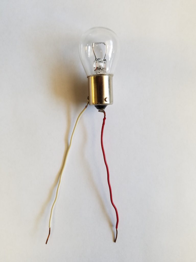
After assembly, check lamp directly on your battery terminals. Caution lamp will become HOT!
Always disconnect the battery or turn off the battery switch (Power Train Battery) prior to disconnecting or reconnecting ECU connectors!
Instructions for WTECII system (two digits on Your shift selector)
For 1992, 1993, 1994, and early 1995 models if experiencing erratic or no display; especially when there is cold weather or have retrieved any trouble codes. Have you seen code 69-32 already? Stop troubleshooting = 100% defective ECU!
Locate the ECU (in most RV’s the ECU is mounted directly to the shift pad). If remote shift selector is used, ECU may be nearby, close to VIM Module or mostly on trucks is mounted close to the transmission (just follow bundle of wires from transmission).
Disconnect the battery first, then unplug the two oval shape ECU connectors and reconnect the battery. Check the B connector with black plastic
backing rear side; for the numbers (the other side backing A connector is either white or blue).
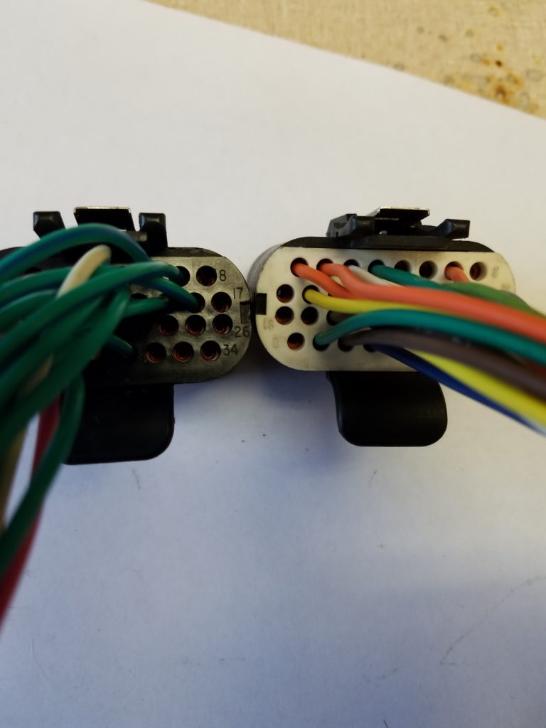
Only 8 numbers from 34 are imprinted (both sides of the row). Insert test lamp leads into corresponding B connector sockets: 9 and 2 then 18 and 11.
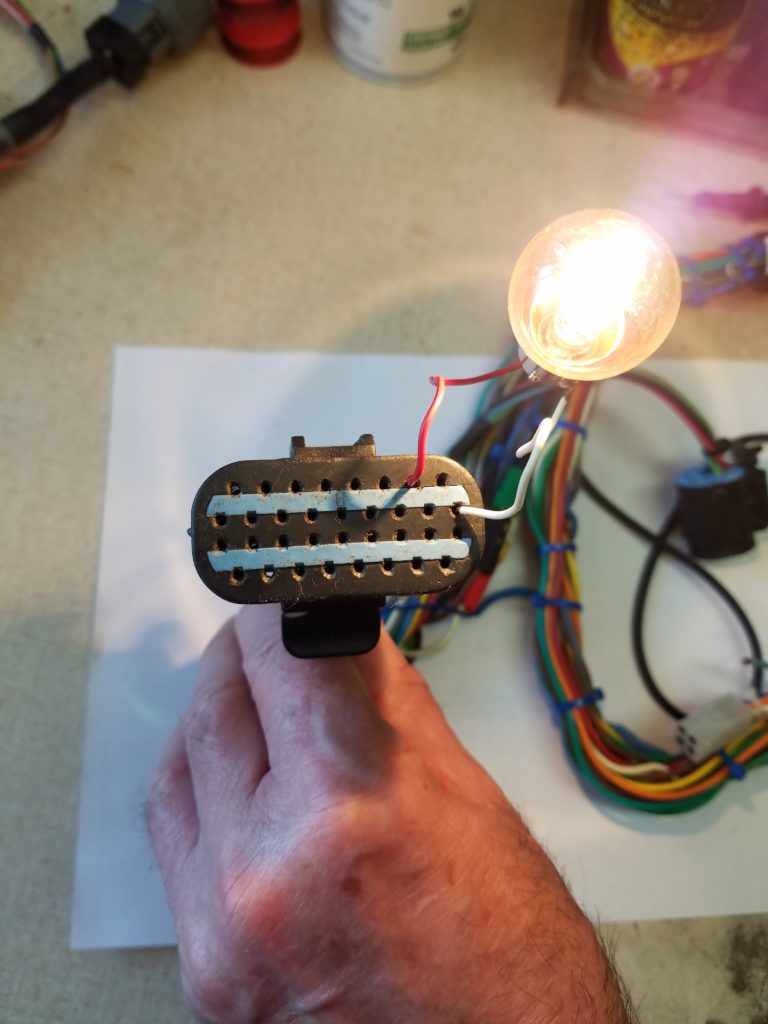
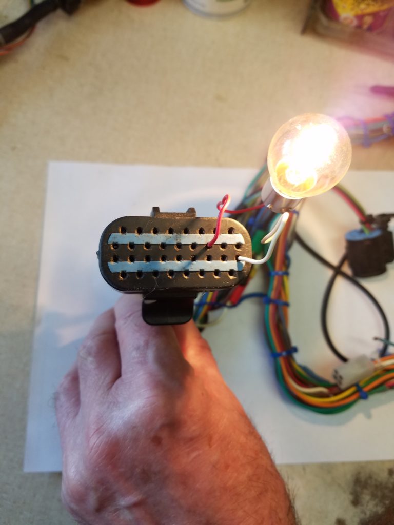
Next turn “ON” Ignition switch and insert test leads to 9 and 12. #9; #18 = BATTERY GROUND; #2; #11 = BATTERY POWER; #12 = IGNITION
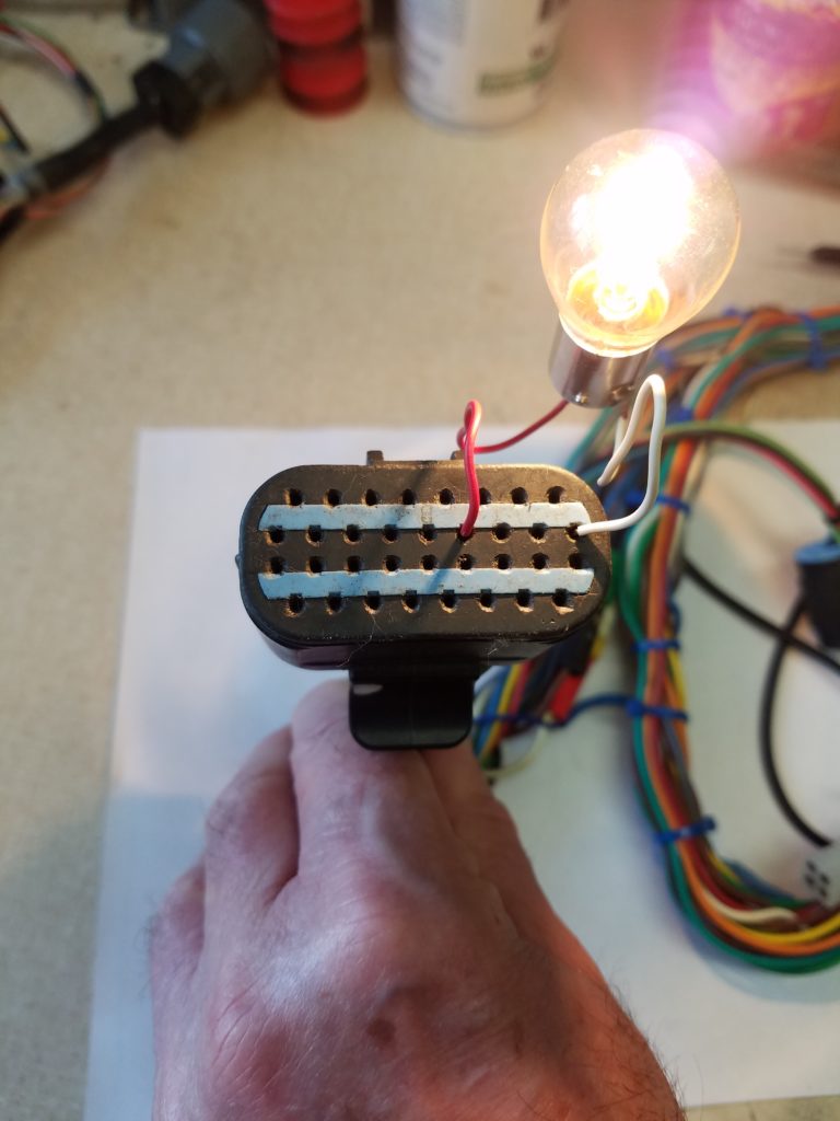
If lamp is bright, the ECU is probably defective unless the display itself is defective. There is no practical method to check display on the vehicle except to swap selector from another vehicle. But, if you do have a remote shift selector, you can check the display using ordinary 9V battery and hookup wire. Remove the two 10 amp fuses from the Vehicle Interface Module (2950986) and connect the 9V battery using bell wire slightly bent on ends; so they can hold inside connector sockets. Negative 9 volt terminal to B connector #9 and 9 volt positive terminal to B connector #2 and A connector #8. After a few seconds remote shift selector should start beeping and show on display “cat eyes “. Just be sure that you have a good connection with wires and sockets.
If display comes “ON”, ECU is defective.
Instructions for WTECIII system (single red digit on Your shift selector)
Have you recently replaced battery and accidentally swapped battery terminals? If “YES”, ECU may be fried beyond repair. If “NOT”, locate the ECU (in most RV’s is near shift selector, close to VIM Module or mostly on trucks, close to transmission (just follow bundle of wires from transmission). Disconnect the battery first, then unplug all three connectors from ECU and reconnect battery. Closely check the GRAY connector for numbers. Insert test lamp leads into corresponding connector sockets: 1 and 32 then 16 and 17.
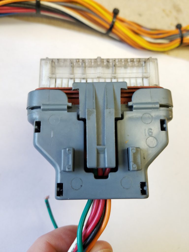
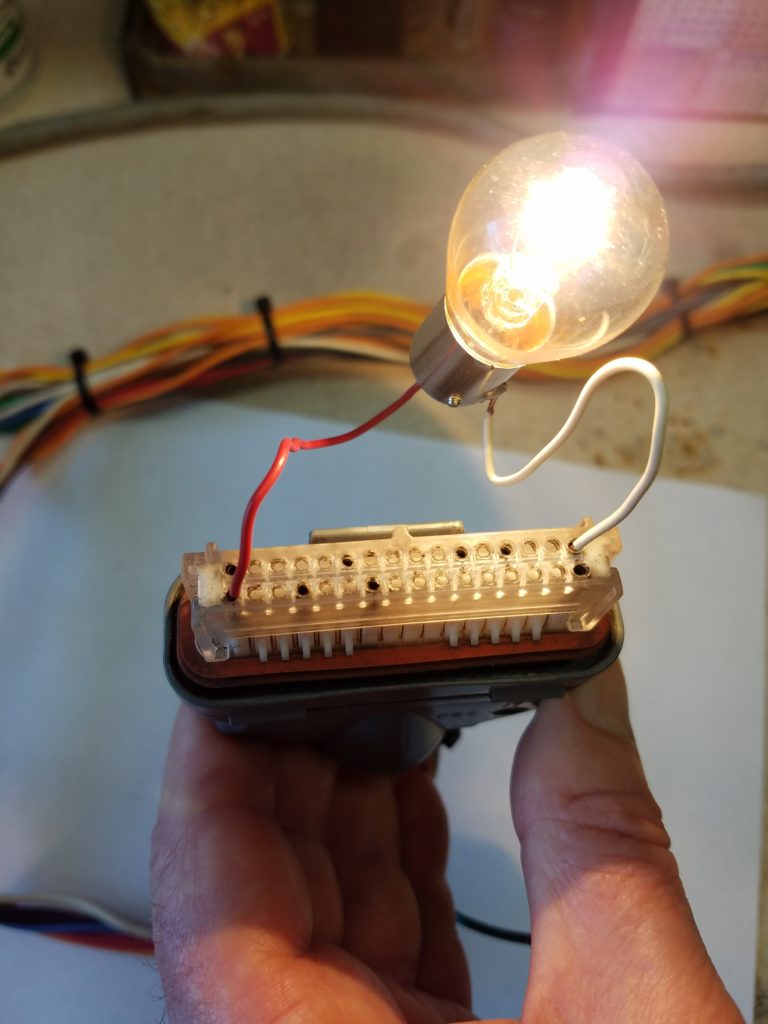
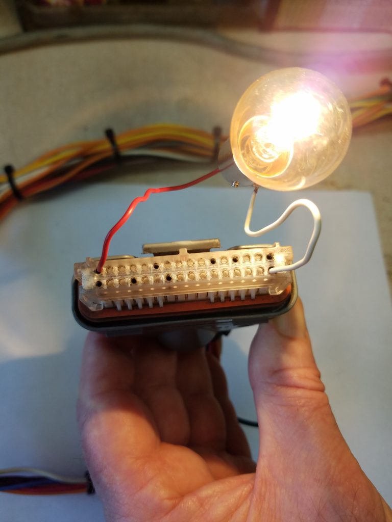
Next turn “ON” Ignition switch and insert test leads to 17 and 26. If cavity #26 is blank, use BLACK connector socket #4. Lamp must glow brightly.
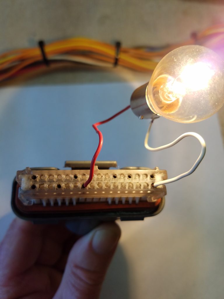
#17; #32 = BATTERY GROUND; #1; #16 = BATTERY POWER; #26 gray or #4 black = IGNITION
Next turn ignition and battery “OFF”, reconnect GRAY ECU connector only, then reconnect battery and turn “ON” ignition. Then very carefully touch gold plated pins #16 and #32 (on ECU side BLACK connector) with lamp test leads. Lamp must glow bright. Then use a voltmeter to check 5V on pin #3 (on ECU side BLACK connector) against chassis ground. DO NOT use test lamp! If no 5V is found on pin #3, ECU is defective.
Also check socket #3 on BLACK connector with ohmmeter against chassis ground. Must be over 4k ohms.
Shift selector can be checked using ordinary 9V battery and hookup wire. Connect the 9V battery using hookup wire which you may have to slightly bent on the ends so they can hold inside BLACK connector sockets. Connect negative terminal to #32 and positive terminal to #3 and #16. During power “UP”, all segments display and RED LED (Mode)will be illuminated for 8 seconds and then display will show “cat eyes “. If one push button “D”,”N”, or “R” is held down during power “UP”, display will show “D”, “N”, or “R” for 2 seconds only. This way you can check push button switches.
If display does not illuminate, the shift selector or harness may be defective. To check the harness, you must disconnect connector located 1/2′ from selector. Then remove strain relief (black plastic) from vehicle harness connector and check closely on the rear side for letters.
“P” = GROUND “R” = POWER “N” = SENSOR POWER
Insert 3 short lengths of hookup wire into sockets “P”, “R”, and “N”. Use a voltmeter to check voltage between “P” and “R” and between “P” and “N”; If your using a 9V battery. If ECU and battery are still connected, insert lamp leads to “P” and “R”, then turn ignition “ON” and with a voltmeter check for 5V in socket “N”. If you do have voltage and there is no display; shift selector is most likely defective. If you do have voltage on ECU pins and not on the shifter connector; a defective harness is indicated.
Check continuity with your ohmmeter between “P” and chassis ground. Should be less than 1 OHM. If the meter reads “open”, (Infinite resistance) find a good ground in the cabin, cut the “P” wire 3″ from connector and reconnect with new ground. If missing 12V – “R”, find “ignition” power, cut “R”, and reconnect with “ignition” power. If missing “N” (5V ), cut “N” and reconnect with “ignition” power.
12V will not damage the shift selector. If one of three last steps will power up the shift selector but has no response to commands. You may have additional harness damage or defective ECU or shifter. In this case, you can send ECU + shifter for free testing (You only pay for shipping).
